Published: Oct 8, 2025 by James K
OutdoorLads LED Matrix
A three-part build exploring the design, hardware, and firmware behind a portable LED matrix for the OutdoorLads DJ booth.
-
OutdoorLads LED Matrix (Part 1: Concept & Design)
- OutdoorLads LED Matrix (Part 2: Build & Hardware)
- OutdoorLads LED Matrix (Part 3: Firmware, Software & Showtime)
In this first part, I’ll cover how the idea came about, the design goals, and how the concept evolved through a potential versions before settling on something that would turn the DJ Booth into an awesome focus piece.
Background
OutdoorLads are a UK group for gay and bisexual men to #GetOutMore in the great outdoors, which I’m a member of. We regularly have “BIG Events”, where we have an evening disco - usually themed! OutdoorLads has its own equipment for this, but it was over 10 years old and was due for a refresh. Since I seem to have inadvertently become known for knowing lots about tech, I was asked to take the lead on this. The whole refresh is a whole other story, so in a nutshell - with a very thorough spreadsheet we ended up with an absolutely awesome setup that is louder and better sounding than the old system, and much lighter too! And most importantly, within budget.
Part of this new setup was a new DJ Booth, which is a truss system - It’s very light weight and is really easy to set up, but it looks very plain and uninteresting. I wasn’t happy with this, and with my love for LEDs and visuals, I knew exactly what I wanted to to.
The Idea
The front of the DJ booth, in my mind, was SCREAMING for a LED Matrix facade to make it really pop. As expected, there were no accessories like this for this DJ Booth, and if you want one of these, they’re usually made bespoke, and are quite expensive!
So this is where James makes one bespoke, and lucky for OutdoorLads, the parts aren’t expensive and my labour of love is free.
Since all the equipment is moved around from venue to venue, the LED Matrix also needs to be transportable - this means not occupying a great deal of space, and be rugged. The design direction I went down, was to have a foldable LED Matrix, that folds in half a bit like a laptop. When open, it fills the entire front of the DJ booth, and when closed, the LEDs are protected inside, and some claps keep it shut.
Requirements
Before detailing the design and build, the following requirements are what I had identified for this project:
- Must fill the whole front of the DJ Booth, and be able to be securely attached
- Must be able to fold up to aid in transportation and storage
- Must be rugged to withstand transportation
- Must be easy to setup by non tech-savvy people
- Must have a decent pixel density (bit of a wishy-washy requirement)
- Must have a selection of kick-ass visualisation effects
- LEDs must be RGB, and be as big as possible
- LEDs must be able to be driven rapidly to sustain a video-quality refresh rate
- Total cost of parts must be below £300
I’ve already used addressable LEDs before in the past - they’re awesome! So using them for this project was a decision I had already made. There’s various different types available - I wasn’t going to bog myself down with one particular type, instead, I decided to look at what different addressable LED packages are available, i.e. the physical LEDs. I’d then chose the addressable LED type based on what is available in the package I want.
Designing Foldable Frame and LEDs
First thing is to get an idea of how this LED Matrix will be constructed. It needs to open out to fill the entire front, and have the LEDs mounted in such a way that they are sturdy and look good from the front, and hide away/protect the wiring and electronics of the LEDs. The Truss DJ Booth that this is being designed for is shown below:
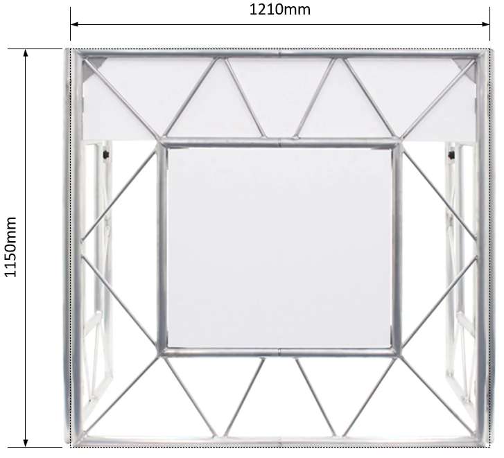
As with most designs that are physical, I did some simple 2D modelling using Microsoft Visio (I always feel some shame in using Visio! I use it all the time at work and I can use it really well). I did this so that I can get a visual indication of what the LED matrix will look like. As mentioned, I want the pixels (I’m going to refer to the LEDs as Pixels in when in the context of the Matrix) to be spaced such that pixel density doesn’t look too “empty”, so that the effects look good. Another key aspect here, is that the physical build will have a structural frame, and due to the matrix being foldable, there will be some frame in the middle of the matrix, two frames in fact - one from each side. I don’t want the frame to add any extra spacing between the pixels on both sides, I want the pixel spacing to be uniform across the whole matrix. So, the 2D models allows me to identify the spacing between the frame join, which governs the minimum spacing.
(By the way, all measurements are metric. mm unless otherwise stated).
Design A
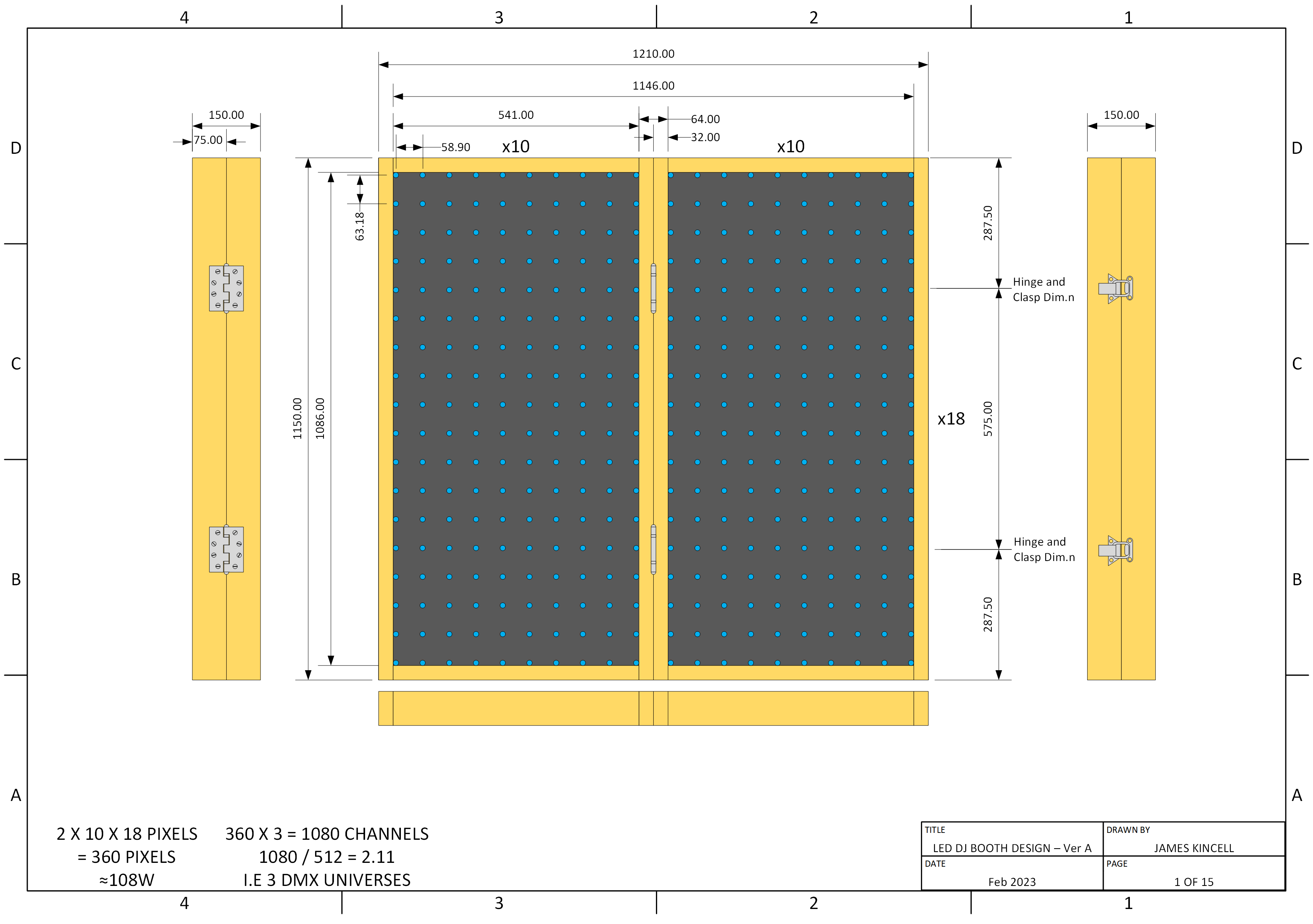
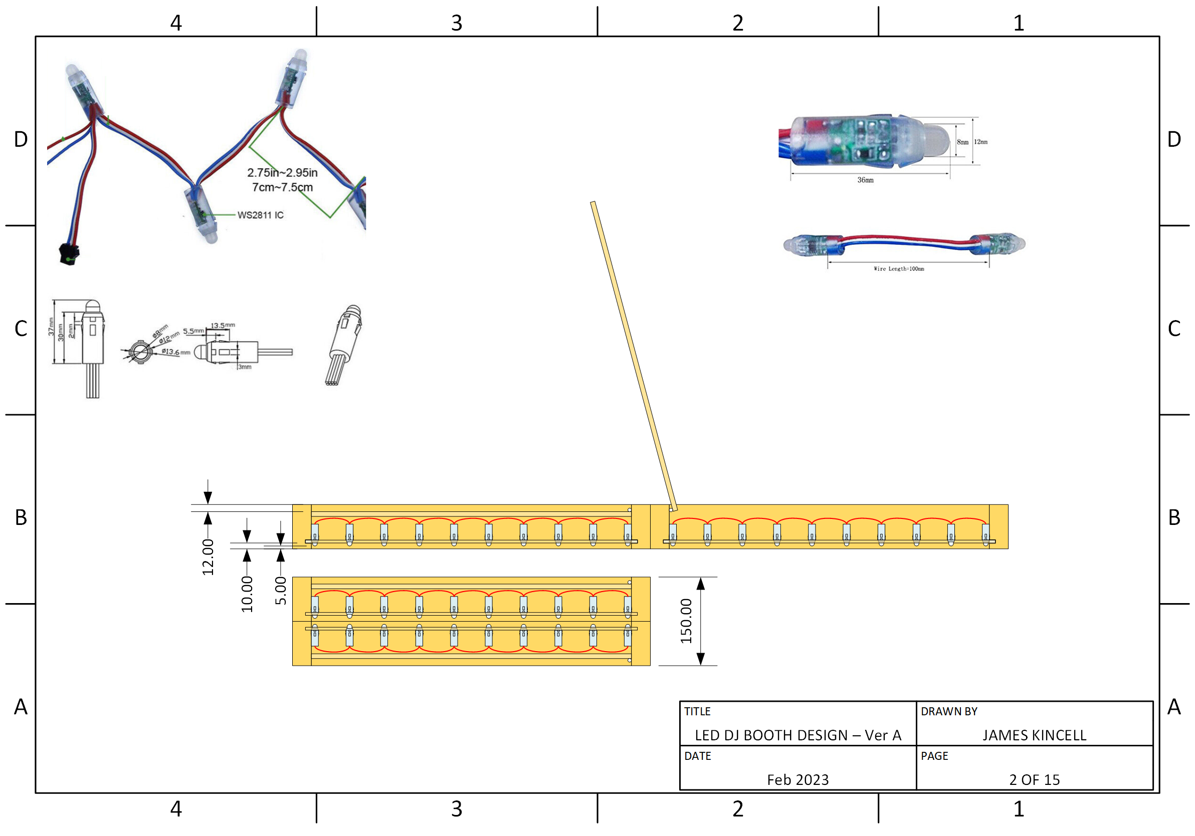
The first design is based around addressable LEDs that are in a string - a bit like Christmas lights. They are 5mm RGB LEDs soldered to a PCB that has the addressable controller, epoxy encapsulated in a mount (I use the word mount loosely, it’s a friction fit mount). These were my first design since I’ve used these type of addressable LEDs before in a project that I did to make some Pac-Man prop boards.
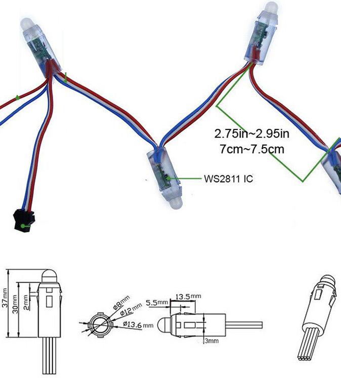
The good thing about these, is that I can space the pixels however I please, to both get the right pixel density, and also fit within the panel size evenly. The down side with , is that they are very deep, so the panels needs to be able to accommodate their depth.
For this design, in order to be able to accommodate the depth of the LEDs, I chose to use 75mm by 32mm timber. I already was not happy with this design - the folded thickness is 150mm - that’s 15cm! That’s too big, clumsy, and heavy. Also, the frame causes a gap of 64mm between the two panels, and the best spreading I could design here was a inter-pixel distance of 58.9mm. This means that there will be a slightly bigger gap between the LEDs at middle, which will be obvious. Not happy with this.
| Thickness: | 150mm |
| Inter-pixel Distance: | 58.9mm |
| Frame Gap: | 64mm |
| Resolution: | 20 x 18 |
| Total Number of Pixels: | 360 |
| Approx. Max. Power: | 108W |
Design B
The first design is good and allows flexibility in pixel density, however it is too damn thick! This makes it difficult to store and transport, plus makes it more clumsy. My second design is with a thinner design, using addressable LED strips - you’re probably familiar with these types of things, they are LEDs etc. mounted to a flexible PCB, and usually come with a self-adhesive back, and they can be found in water-resistant versions where they are covered in a flexible encapsulation. These are really thin! So it means I can make the frame thinner than with Design A. The downside though, is that they have a fixed spacing between the pixels, so less flexibility when designing in to the frame.
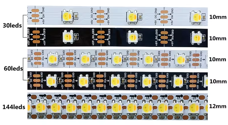
30 LEDs/m ≈ 33mm between LED centres
60 LEDs/m ≈ 17mm between LED centres
144 LEDs/m ≈ 7mm between LED centres
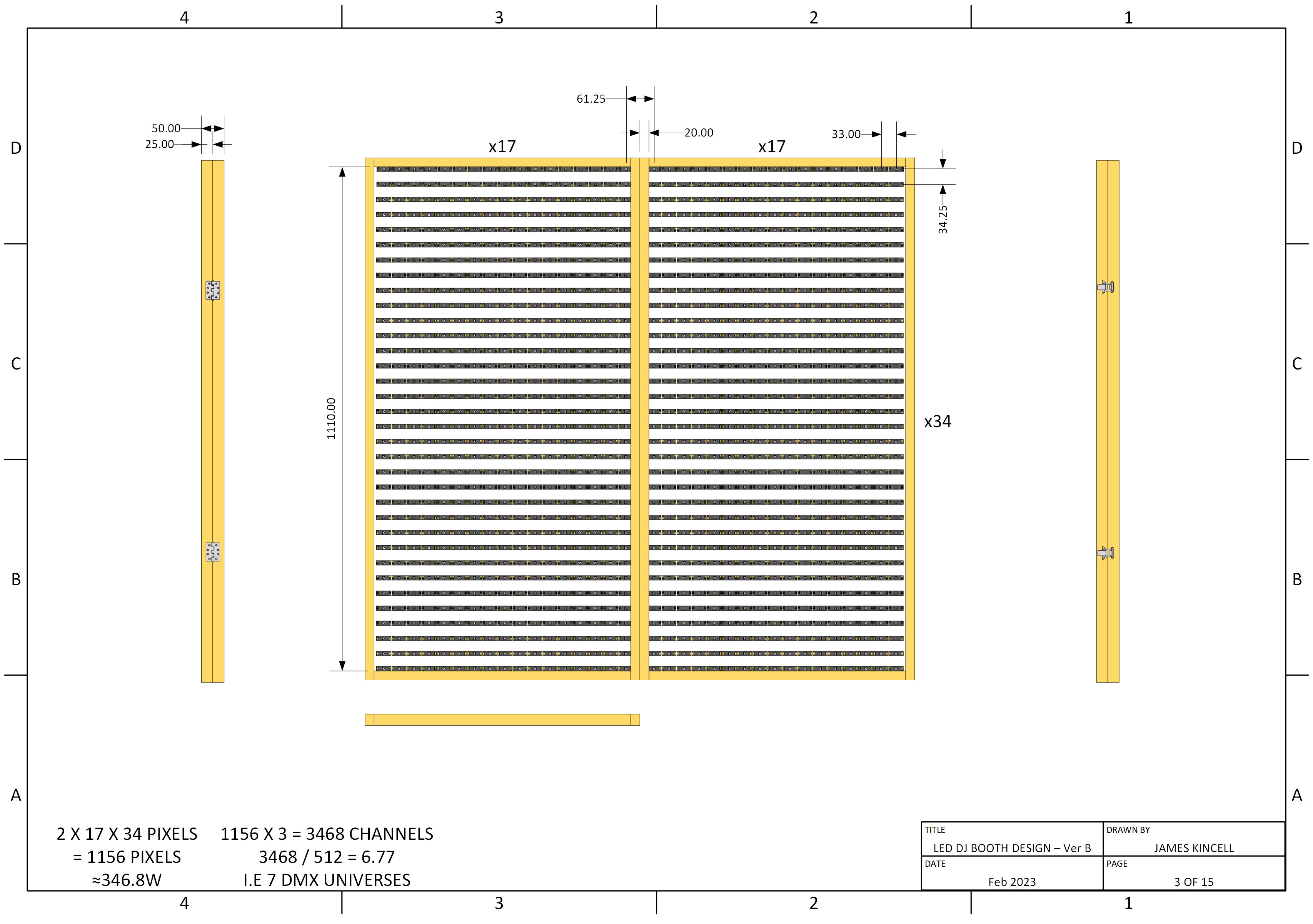
For this design, since the strips are thin - about 2.5mm, the frame can be much thinner than Design A. For Design B, I chose to use 25mm by 20mm timber. This results in a folded thickness of 50mm, i.e. 5cm - that’s a third of the depth of Design A! So this is much thinner and lighter. With this timber, the frame causes a gap of 40mm between the two panels - this means that the only strip type that would work is the 30 LEDs/m type, with a distance of about 33mm between the pixels. This is annoying, since the pixel distance is closer than the frame gap of 40mm, so it would mean that there is a bigger gap between the pixels at the middle seam, something I really want to avoid. To make matters worse, it isn’t possible to get the spacing the same in the vertical axis, and it would mean a vertical pixel spacing of 34.25mm.
So, this design already has it’s down sides despite being thin. And there’s more… If one pixel fails in the future, it would be very difficult to replace a single pixel. The LED strips would have to be attached using the pre-applied self-adhesive tape. I have very little confidence that this would last, and fear that the panels would fall apart too easily, unless a clear perspex front was added on the front, adding to weight and cost, and making it even more difficult to replace a pixel. And then for the final negative point, I think the strips would look a bit cheap and amateur.
| Thickness: | 50mm |
| Inter-pixel Distance: | H: 33mm, V: 34.25mm |
| Frame Gap: | 40mm |
| Resolution: | 34 x 34 |
| Total Number of Pixels: | 1156 |
| Approx. Max. Power: | 346.8W |
Design C
Okay so we’re not off to a good start with the first two designs! I thought I was a bit stumped, but there was something in the back of my mind - the Design A LEDs gave great flexibility with pixel spacing, and looked more professional, but it was the damn enclosure thing that they are encapsulated in that is causing the problems. If I could have those LED strings without the mounting encapsulation thing, that would probably be perfect.
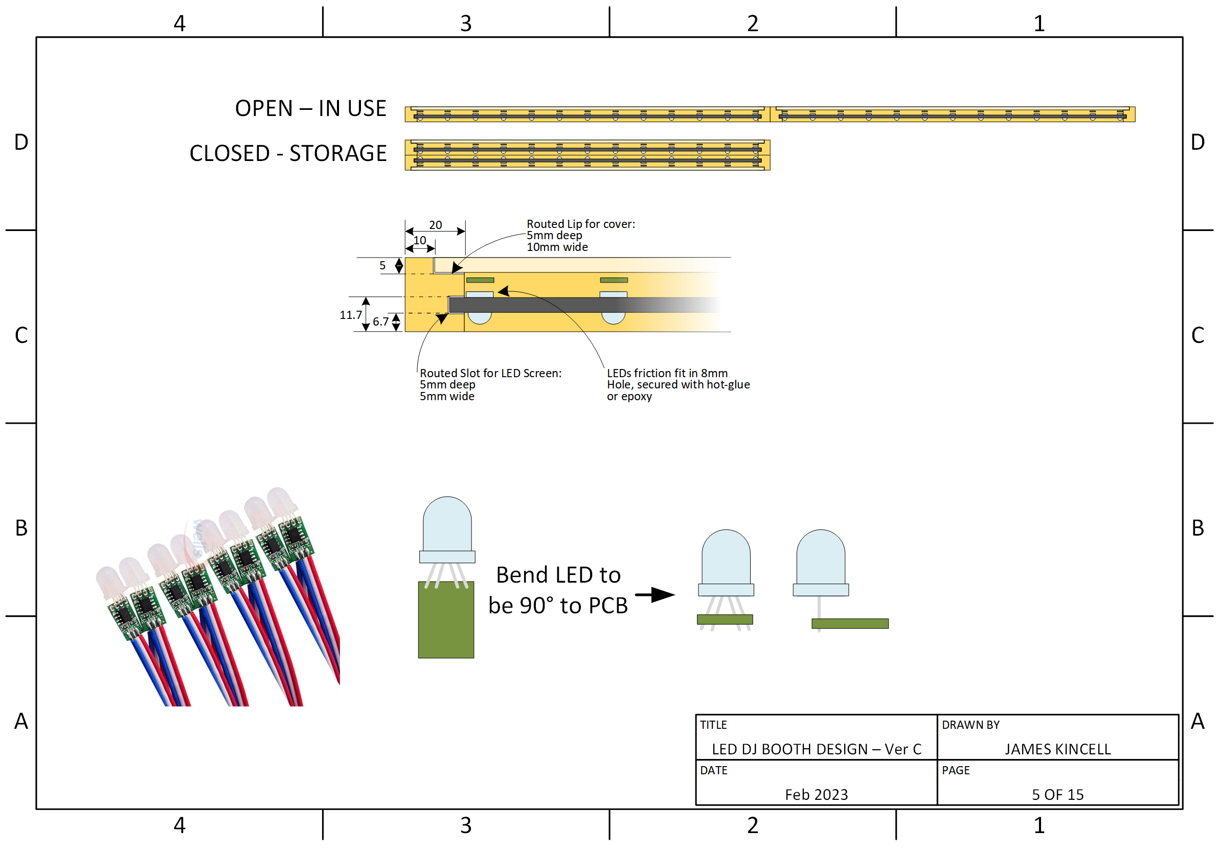
Well, after lots and lots of trawling of the internet, it turns out you can indeed get the Design A LEDs in their raw form, but they were hard to find! With these, the LED is bent 90° as though they are ready to go into the plastic mounting encapsulation thing, but I knew that I could bend the LEDs back to their original position, which would reduce their depth. Plus the lack of a mounting bezel on the LEDs means that the LEDs on the middle can butt up to the frame, to reduce the spacing caused by the middle of the frame. The addressable LEDs in this form factor use the WS2811 IC.
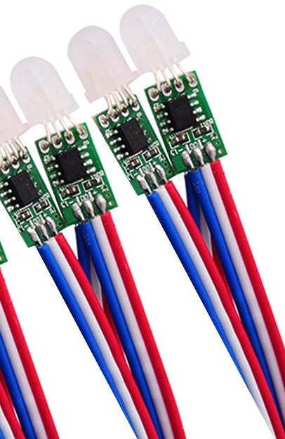
This design combined the positives of Design A with the Positives of Design B:
- Less bulky design, 50mm thick when folded
- Individual LEDs that can be spaced however I want. Can avoid the visible gap of the middle, and the LEDs can be more easily replaced should one of them fail in the future.
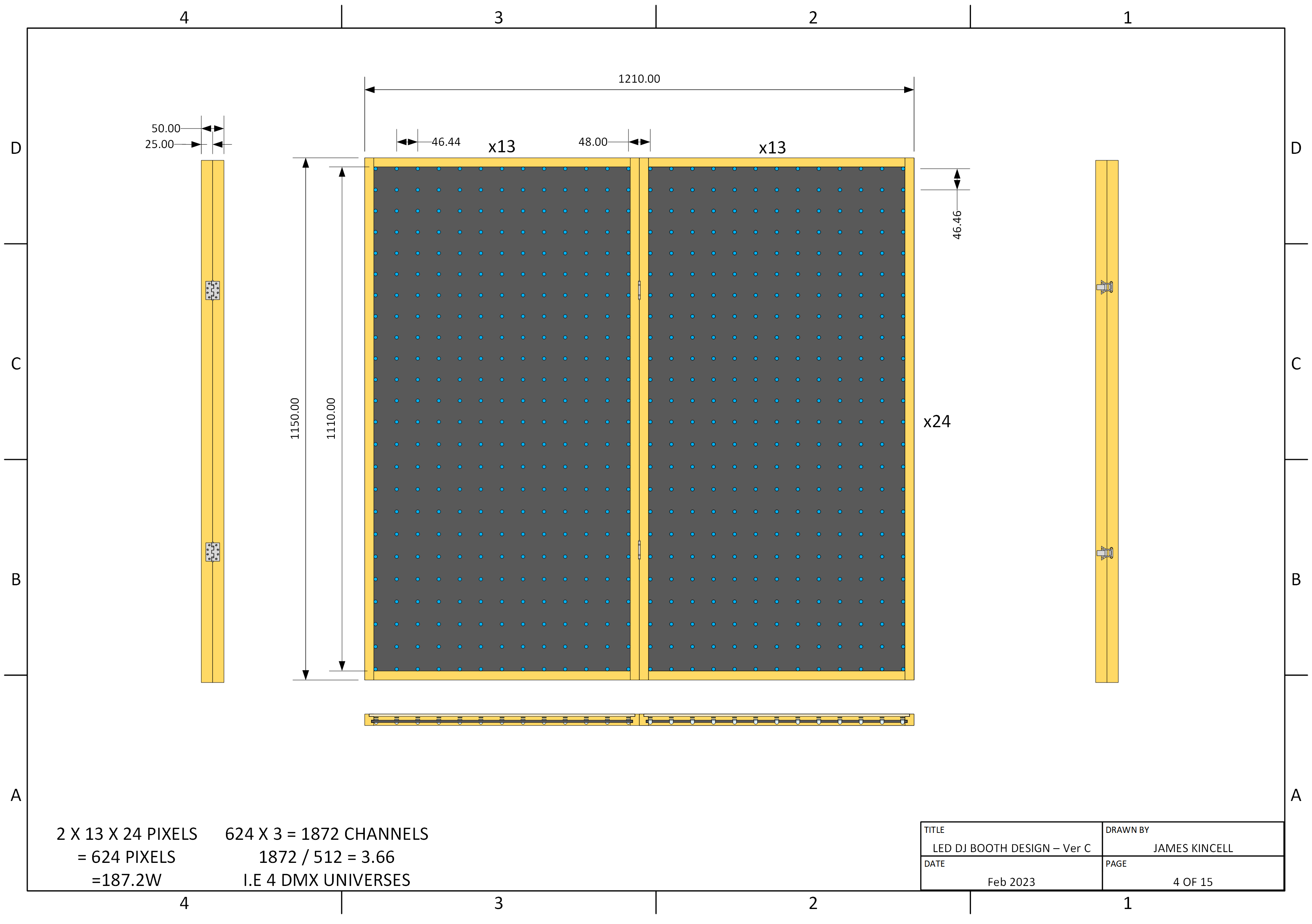
With this design, when the LEDs are butt up to the edge of the frame in the middle, the horizontal pixel spacing is 48mm. While it is possible to make the rest of the pixels spaced the same, it meant that the outer edges had no pixel, and it looked odd. As a compromise, I made the pixel spacing 46.44mm, which allowed me to horizontally squeeze in 13 pixels in a single frame, with the middle pixels only being spaced by 1.56mm more, which I don’t think will be noticeable. I was also able to fit 24 pixels in the vertical direction at the same pixel spacing of 46.44mm.
| Thickness: | 50mm |
| Inter-pixel Distance: | 46.44 |
| Frame Gap: | 40mm |
| Resolution: | 26 x 24 |
| Total Number of Pixels: | 624 |
| Approx. Max. Power: | 187.2W |
Chosen Design
It’s probably no surprise that Design C is the winner! To justify this…
Firstly, The LEDs for this design allow the frame to be a reasonable size, such that the frame is rigid yet not big and clunky. The smaller frame reduces the frame width in the middle, meaning the pixels can be reasonably dense. The reduced frame width means that the inter-pixel distance (between the pixel centres) in the middle of the panel are 48mm, while the rest of the pixels have an inter-pixel distance of 46.44mm. This means that there is only a marginal difference in pixel spacing at the middle, which shouldn’t be noticeable. The pixels can be mounted in a panel of sheet wood, which has a more professional appearance than LED strips.
That’s all for this post, next up is building this and making it happen, check it out in Part 2: Build & Hardware.

