Published: Nov 8, 2025 by James K
Oh It Doesn’t Work!
We recently got a Hot Tub, always wanted one and finally we got one! It wasn’t new, a friend of our amazing neighbours Hilary and Neil had one that he wanted to sell on as he wasn’t using it any more. The Hot Tub is a Typhoon by Watkins/Hot Tub Superstore, a 6 seater. He insisted that it was fully working, but as you guessed, it didn’t quite work and we had a cold tub.
The Problem
After spending what felt like an eternity burying armoured cable (SWA) to the garage and fitting a garage consumer unit to be able to have power for the hot tub, we filled the hot tub and turned it on with excitement.
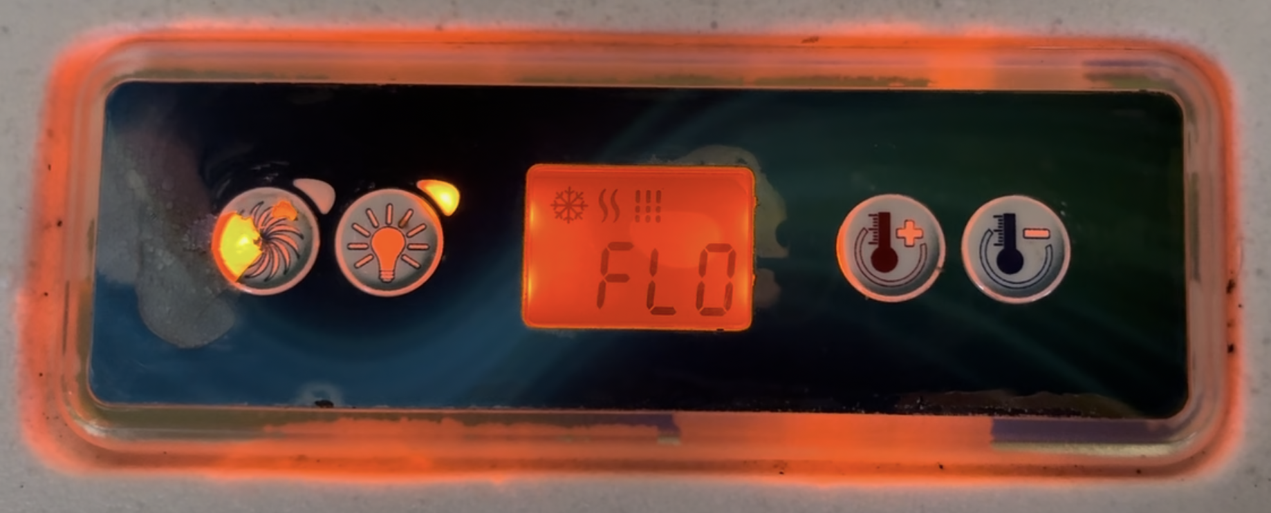
The hot tub has two speeds; low and high. The low speed is used for circulating water for both the filter cycle and the heating cycles, as well as a low speed when in the tub. The high speed is used for powerful jets. The high speed worked, but the low speed didn’t. This meant, that when it is trying to heat the water, there is no flow, and this is detected, and thus the water is not heated, since water flow is required for safe heating. The controller is doing its job right here at least.
Investigation
I need to now figure out why the low speed is not working. It’s not completely dead, just the low speed. Inside the hot tub there is a Gecko IN.YJ-2, which is a fairly standard hot tub controller. It is an EU variant for 230Vac, and I have suspicions it is a specific variant for Watkins/Hot Tub Superstore. Using the power of that internet, I was able to see that there are two separate outputs for the pump - a low output, and a high output. So, now we hone in on the problem! Is it the pump that is broken, or the output from the controller?
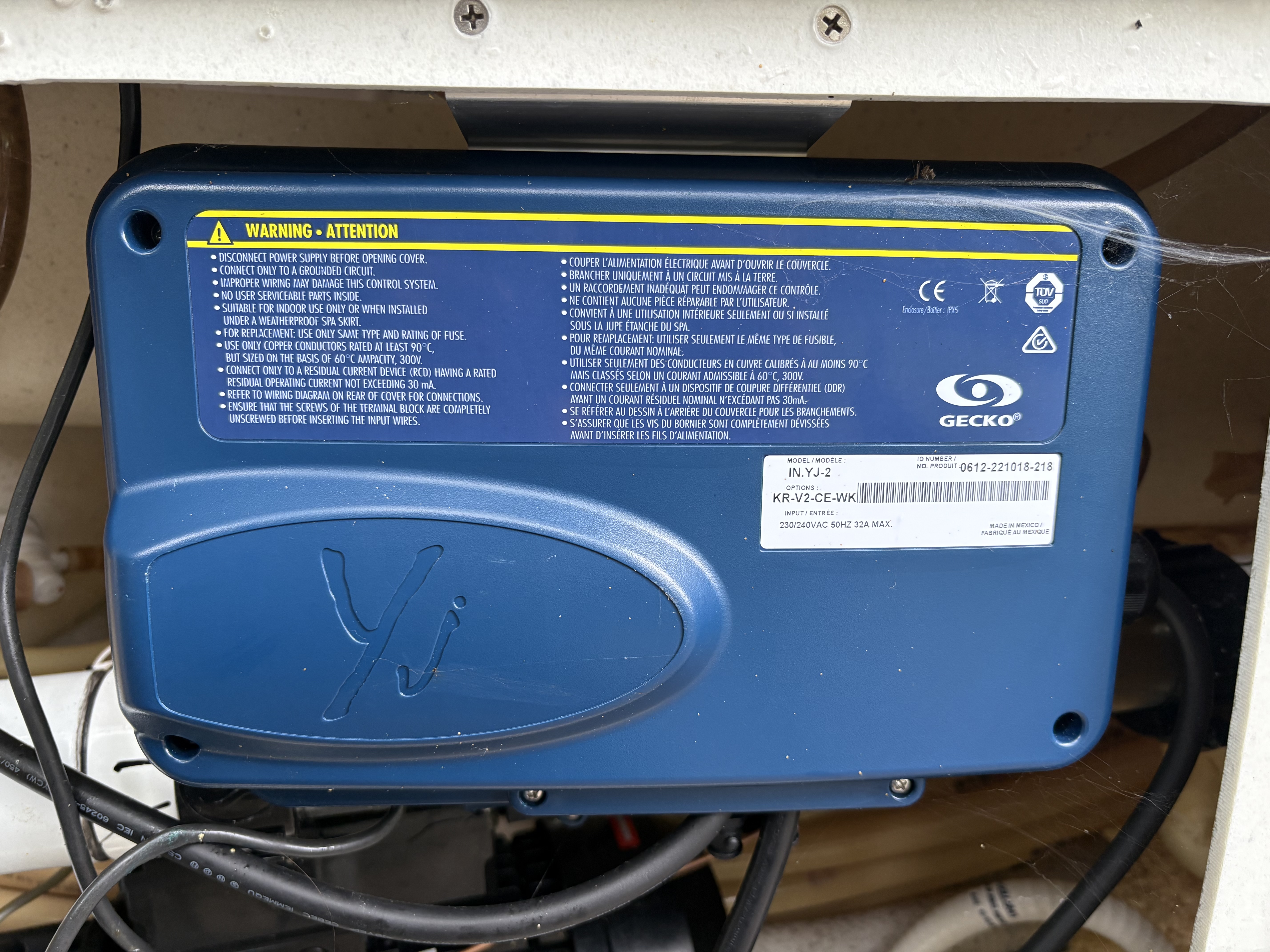
The Pump is made by Watkins. The information panel is very helpful - it is a single pump assembly, but presumably contains two separate motor windings; one for low, one for high. By the way, I have zero familiarity with hot tubs so this is all brand new information to me as I go along.
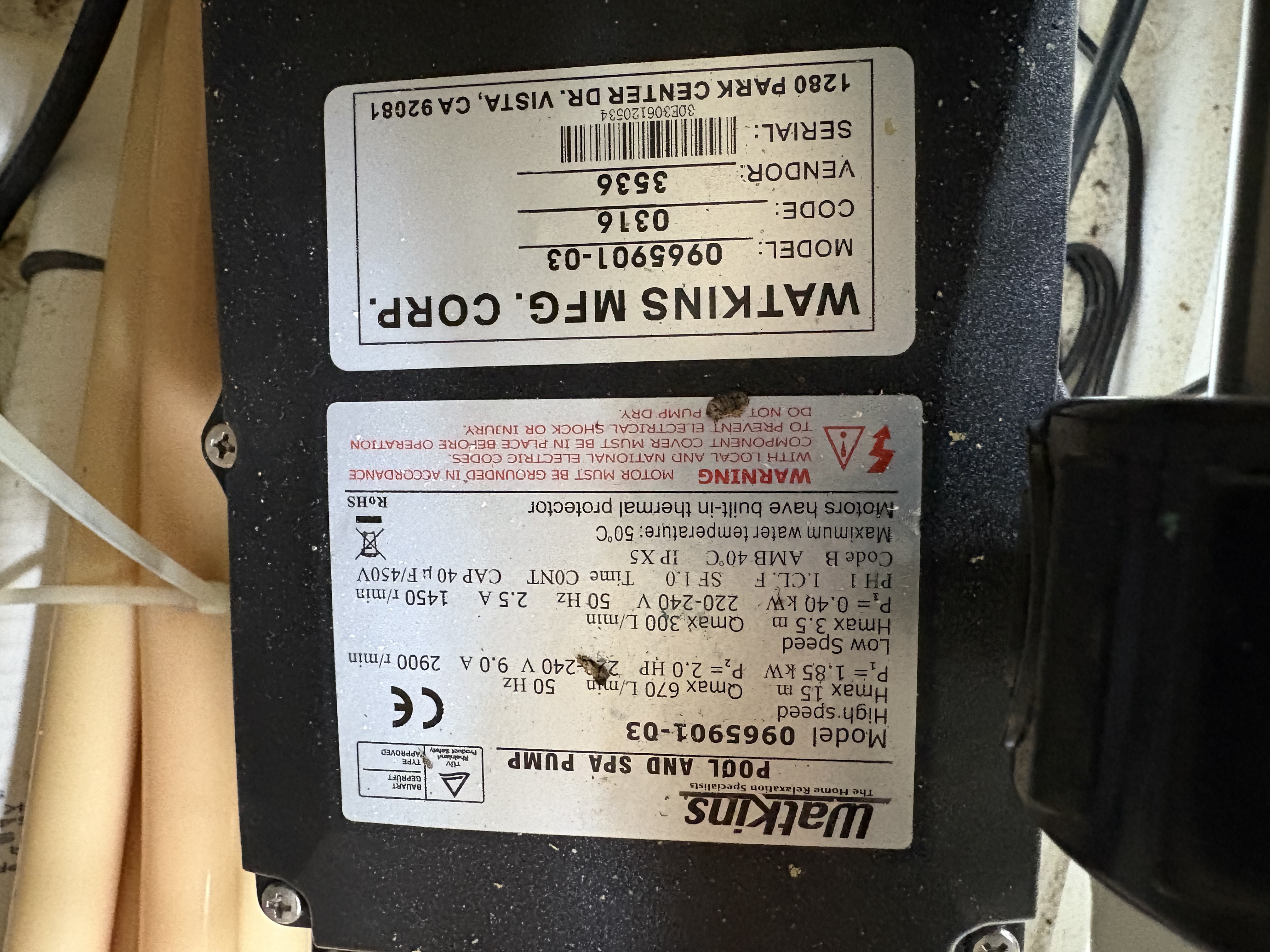
Now onto opening the controller, the bit I was excited about! Very conveniently, there is a legend on the inside of the lid. It isn’t tremendously helpful, but it’s useful. There are four wires from the pump, and these are on the legend, but it doesn’t explain what they are. But I had it mostly figured out:
| Brown | High or Low Pump |
| Black | High or Low Pump |
| Blue | Neutral |
| Green-Yellow | Earth |
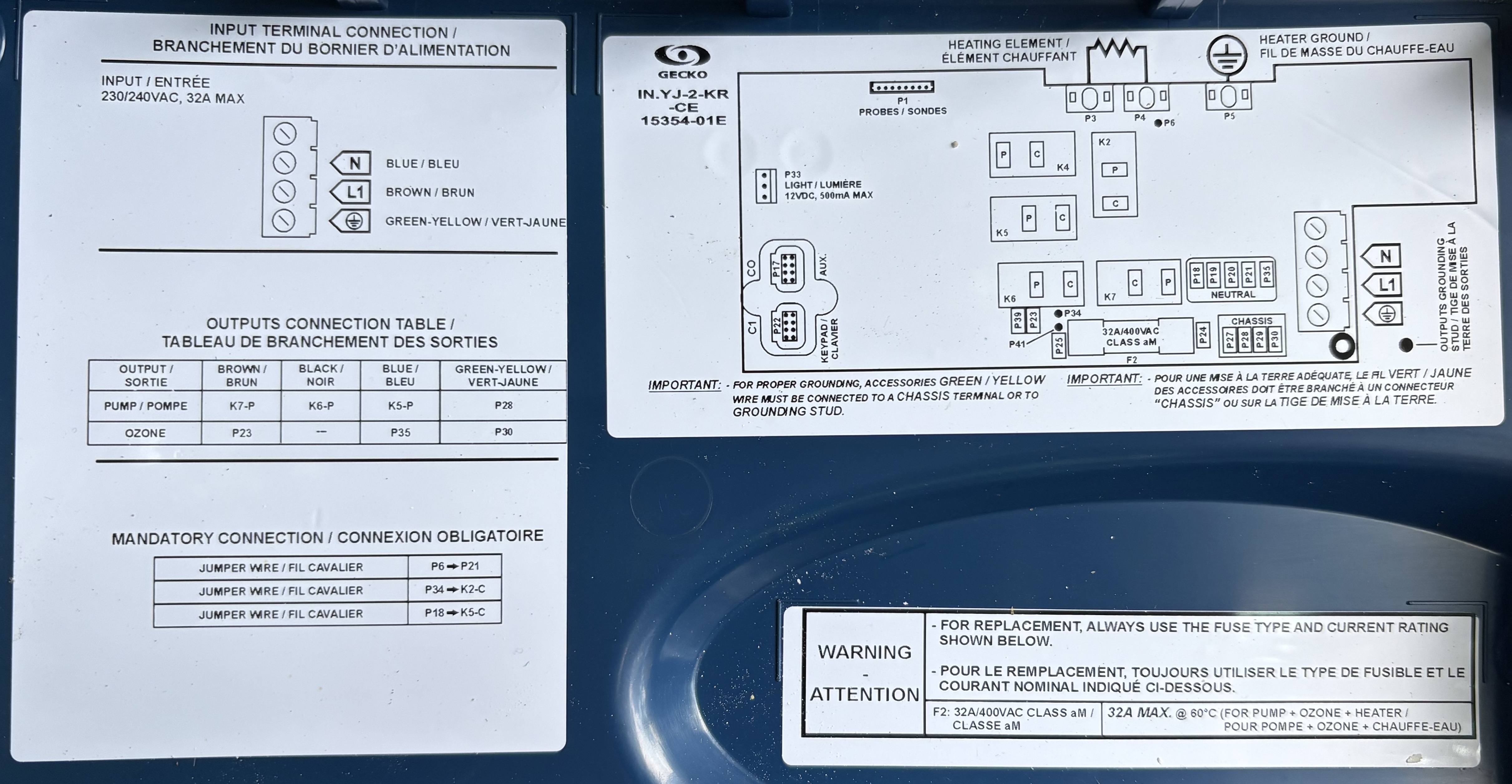
Blue is normally neutral, but to make no assumptions, we can see that the blue wire goes to a relay, and the other contact of the relay goes to a NEUTRAL connector on the PCB. And again with the Green-Yellow, this goes to a grounding lug. It’s obvious, yes, but I’ve seen lots of dodgy equipment before where common colours are not used for their common use, so it’s good to never assume!
So, we have a black and brown wire, one of them is the low pump, and one of them is the high pump. There are three possible causes for the problem:
- The low speed pump winding is broken
- The low speed output relay is broken
- The output drive for the low speed relay is broken
I needed to identify which relay/colour is which, and if the low speed pump is working. Being EXTREMELY CAUTIOUS working with live electronics, I used my multimeter to identify what the output relays are doing. Using the legend, we can see that the pump wires are all connected to the “P” contact, and the “C” contact is unconnected.
| State | N Relay (K5) | Brown Relay (K6) | Black Relay (K7) |
|---|---|---|---|
| Off | Neutral | 0Vac | 0Vac |
| Low | Neutral | 0Vac | 0Vac |
| High | Neutral | 0Vac | 230Vac |
The “C” contacts are all always at 230Vac, meaning this is the common of the relay - the 230Vac will be fed to it via the PCB contacts on the bottom. So, what does this information mean? Well, we know that the high speed works, and it is the black wire that becomes live when it is put into high speed operation. So, that means that the brown wire is for the low speed.
I now wanted to determine if the low speed pump winding works or not. Very conveniently, we have the “C” lugs that are always at 230Vac! So, I disconnected both low and high (just in case, don’t want to have both windings operating together), and connected the brown wire to one of the “C” lugs, as shown below:
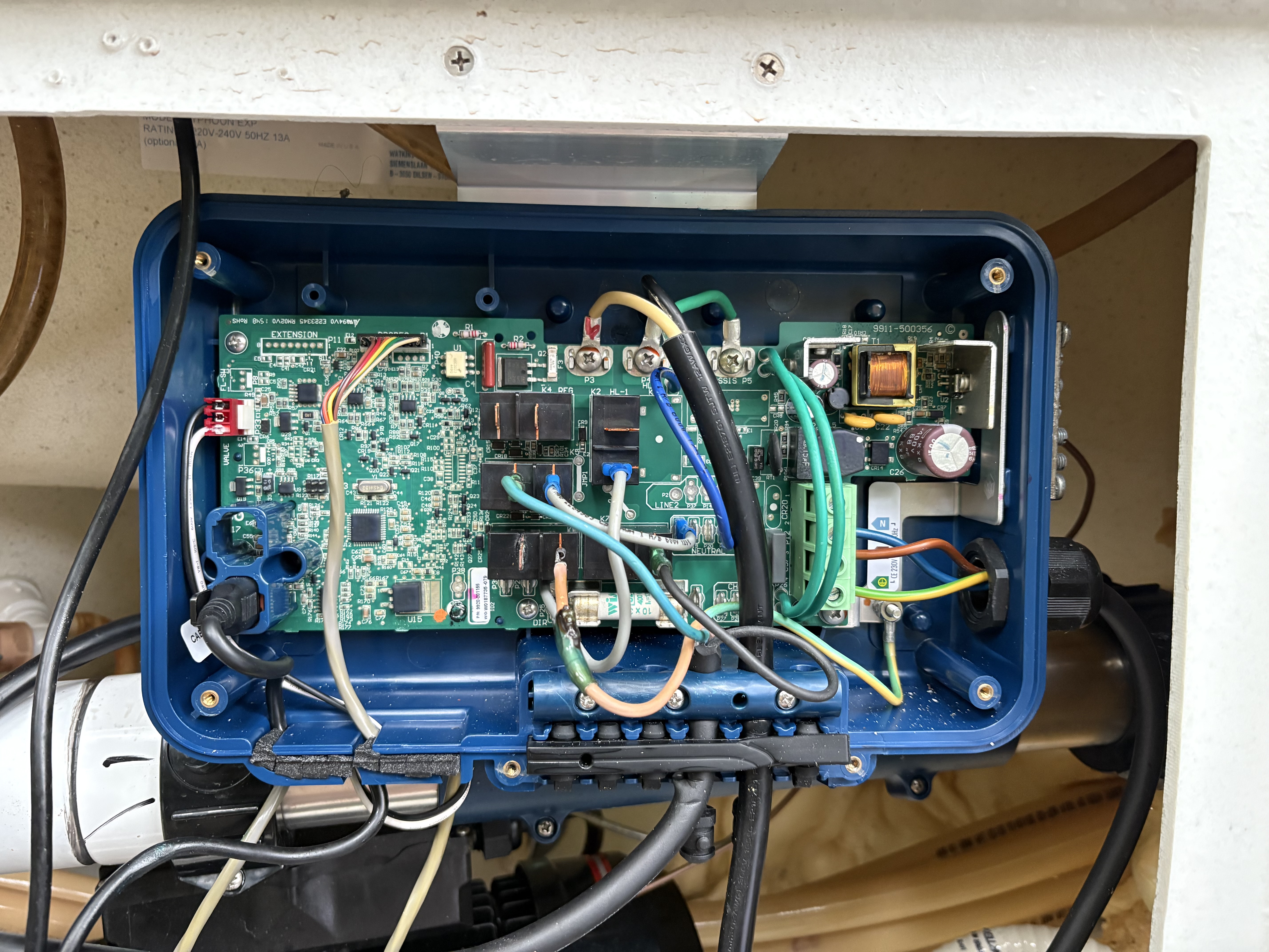
AND IT WORKS!! This means that it is not the pump that is broken, so it must be a problem with the controller, i.e. cause 2 or 3 from above.
I did a quick measure of the heater element to check it, and it measured 30.3Ω when cold. So it’s not shorted or open. To do a quick check, It is rated at 2 kW at 240Vac, so using P=V²/R, the power would be 1.9 kW - seems okay to me.
So, with the low speed pump jerry rigged into operation, I decided to leave it and see if the “FLO” error is gone, and thankfully, it never returned and the hot tub started heating.
Fixing It
So the problem is either a bad relay, or bad relay drive. I had a lucky break here - I did some more measurements of the output of the K6 relay without the low speed wire connected, cycling the speeds, and every now and then, I would measure about 2.5Vac on that pin - this means everything!! What this tells me, is that the relay is getting energised, but the contacts are degraded. Thinking about it, this makes sense - the hot tub is 10 years old, and has been filled for most of that time, so, for 10 years, the low speed pump has been turned on and off automatically as the hot tub does its filter cycled and heating cycles. That is bound to cause the contacts of the relay to wear out and see the burden of high current switching.
I took the control board out of the blue unit, and took it inside to my home-lab. The relay is a Matsushita ALF1TF12 - Matsushita is Panasonic, and this relay still exists albeit with Panasonic branding now.
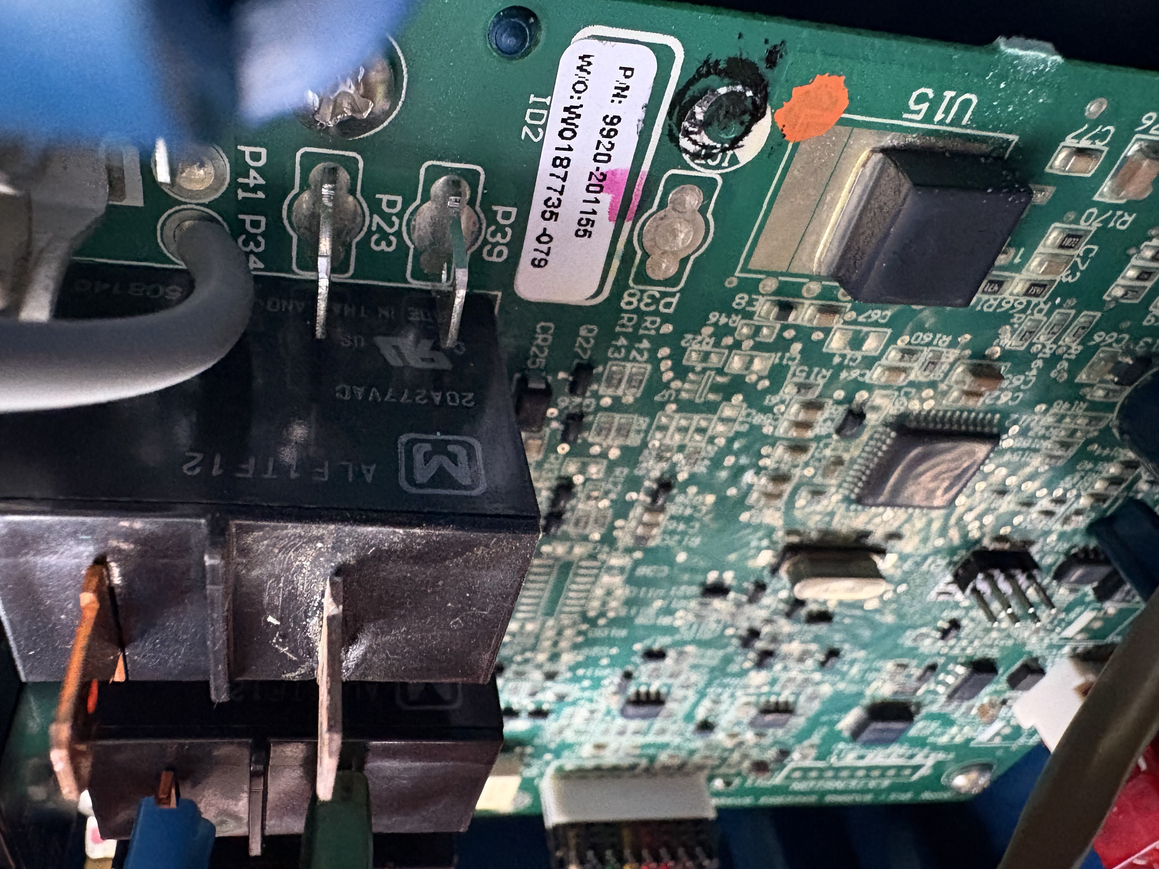
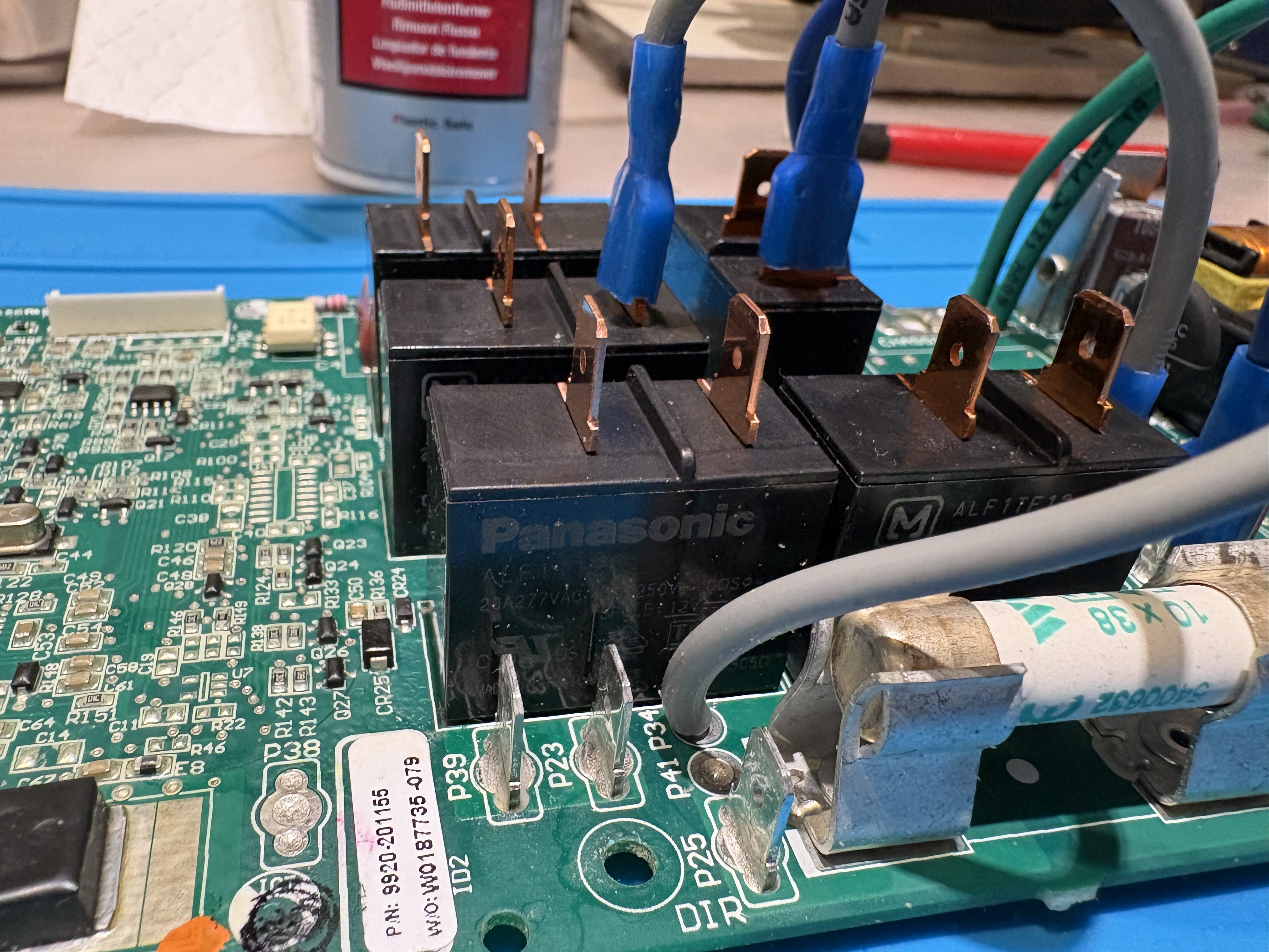
So, I ordered four Panasonic ALF1T12 relays from RS - one to replace the broken one, and three as spares. I removed the old relay, and, curiosity got the better of me (c’mon, I’m an engineer!) - I opened it up to have a look at the contacts, and yes, as suspected, the contacts are completely jiggered:
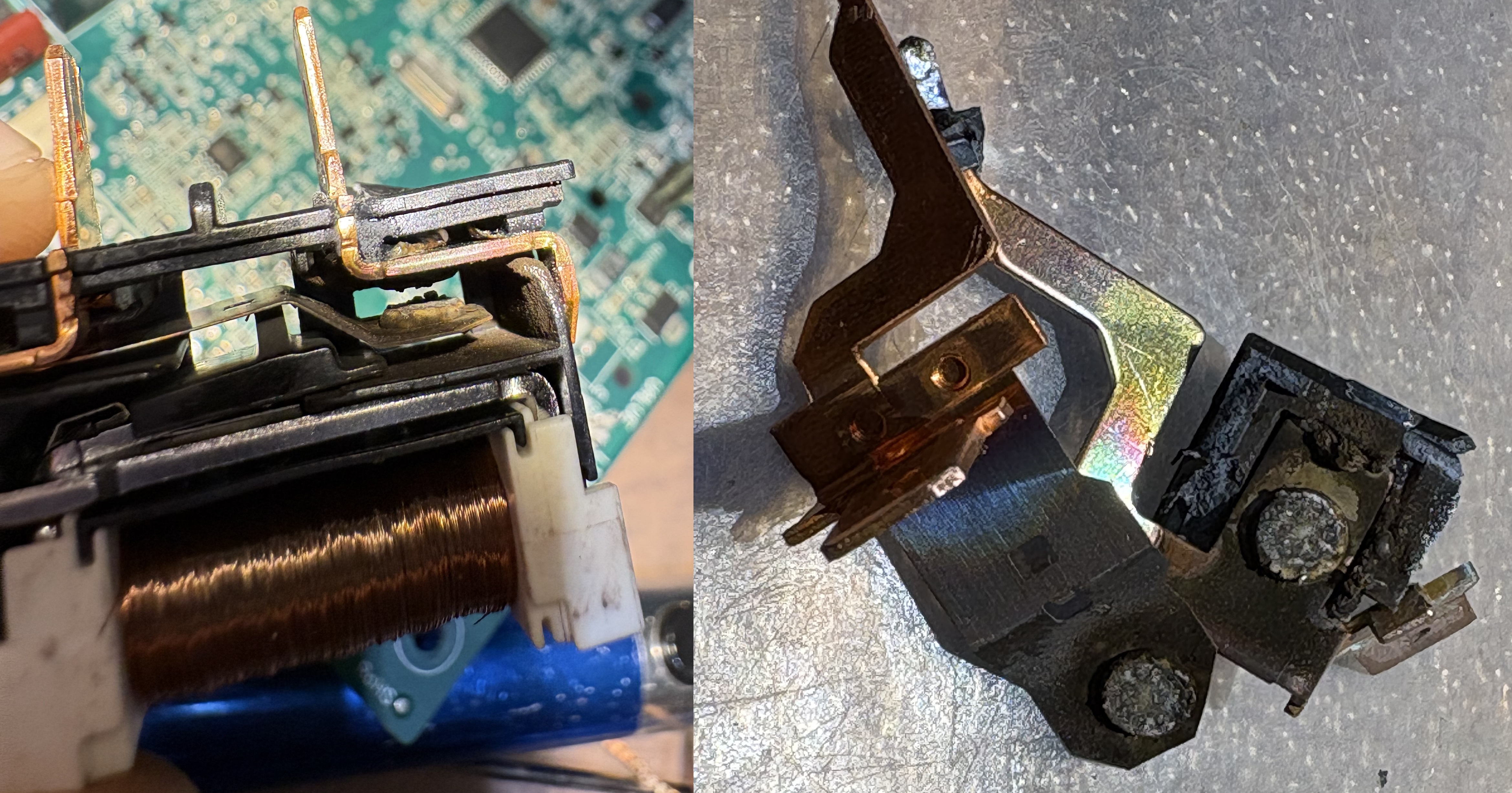
Whipped off the old relay, and fitted the new one:
Testing It
Put the board back into the controller housing, reconnected it, and hoped for the best. And it works! The low pump comes on automatically when power is applied, part of its start up checks. And then once it detects the flow, it starts heating the water. And now, the cold tub is a hot tub! So happy!
The great thing about doing this, is if we’d got a hot tub technician out for this, I think the verdict would have been “buy a new controller” - costing money for the techician, and about £300 for the new controller. This fix cost just shy of £4 for a new relay - so a very pleasing result.
Another little bit of information, this hot tub comes as “Plug-and-Play” with a 13A UK Plug, but in this configuration the heater can only be operated when the pump is at low speed. When at high speed, the heater will not operate, to restrict current on the 13A supply. Thankfully though, you can change a the “Low Level Configuration” to put it into high-current mode which allows the heater to operate while at high speed. So, I removed the cable with the 13A plug, and hard-wired it into an isolator switch with some new 6mm H07RN-F cable. With it in the high-current configuration, the water temperature never drops while using it.
So now, happy hot-tubbing! Perfect for a little relax after a hard day of electronic engineering work!

